
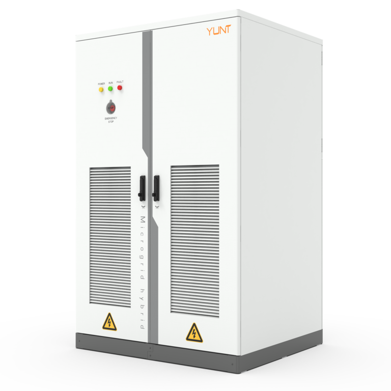
Problem statement: why commutation overlap still causes outages
Modern power-critical facilities increasingly depend on static transfer switches to sustain uninterrupted service. The problem is concrete: when thyristor (SCR) units in an STS fail to cleanly relinquish conduction before the opposing device takes over, commutation overlap occurs. That overlap can produce momentary voltage distortion, thermal stress, and—for sensitive loads—service interruption. Facilities in Dubai financial data halls and other high-density sites have experienced nuisance transfers traceable to inadequate commutation tolerance, so the matter is not theoretical.
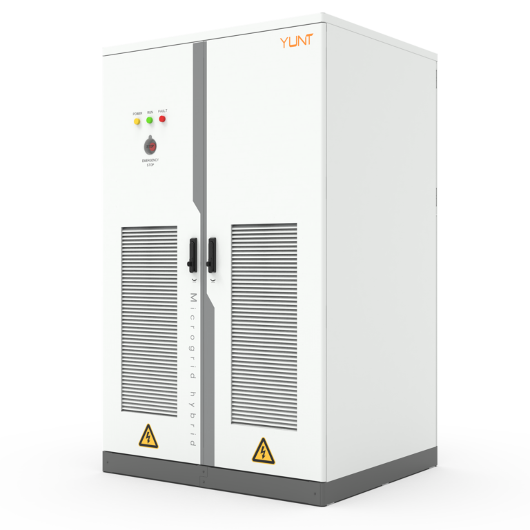
Hardware principles that prevent commutation overlap
At the heart of a reliable STS are three interlocking hardware features: fast turn-off capability at the gate driver, precise zero-crossing detection, and controlled snubbing networks. Gate drivers that force a rapid decline in an SCR’s anode current shorten the window where overlap can occur. Zero-crossing detection aligns switching actions with line voltage phase, reducing stress on semiconductor junctions. Snubbers and RC damping limit voltage overshoot during transfer. Together, these elements lower the probability of simultaneous conduction, preserving both supply integrity and thyristor lifetime.
Design tolerances, testing parameters, and real-world validation
Designers must specify explicit tolerances for overlap time (for example, maximum 50–150 microseconds depending on system fault current) and verify them through timed transfer tests. Verification should include step-change load tests and timed short-circuit simulations with defined parameters: peak fault current magnitude, decay time constant, and measurement windows for overlap duration. A real-world anchor: engineers in Dubai’s data halls often require witnessed factory testing under defined load profiles before acceptance—this practice has reduced site failures by measurable margins. Manufacturers and commissioning teams call these acceptance tests the timed commutation profile, and they form the core evidence for operational reliability.
Implementation choices: thyristors, IGBTs and hybrid architectures
Thyristor-based STS remain common because of robustness and low conduction loss, but IGBT modules and hybrid designs offer finer turn-off control and shorter switching intervals. Hybrid architectures place fast IGBT elements in series with SCRs to shape turn-off and absorb transient energy, effectively narrowing overlap windows. The trade-offs are clear: hybrids reduce overlap risk at the expense of increased component count and thermal management needs. Selective use of such architectures should reflect measured overlap tolerances demanded by the load, not marketing claims.
Common engineering mistakes and operational traps
Design teams often under-specify gate driver margin, neglect snubber energy ratings, or omit timed coordination tests on-site—errors that invite overlap events. Field-side mistakes include inadequate cabling segregation and delay-inducing control latency from poorly segmented PLC logic. A short aside—commissioning schedules frequently underestimate time needed for repeated timed transfers—this causes rushed verification and later surprises. To avoid these traps, combine component-level validation with full-system timed transfer sequences under realistic load.
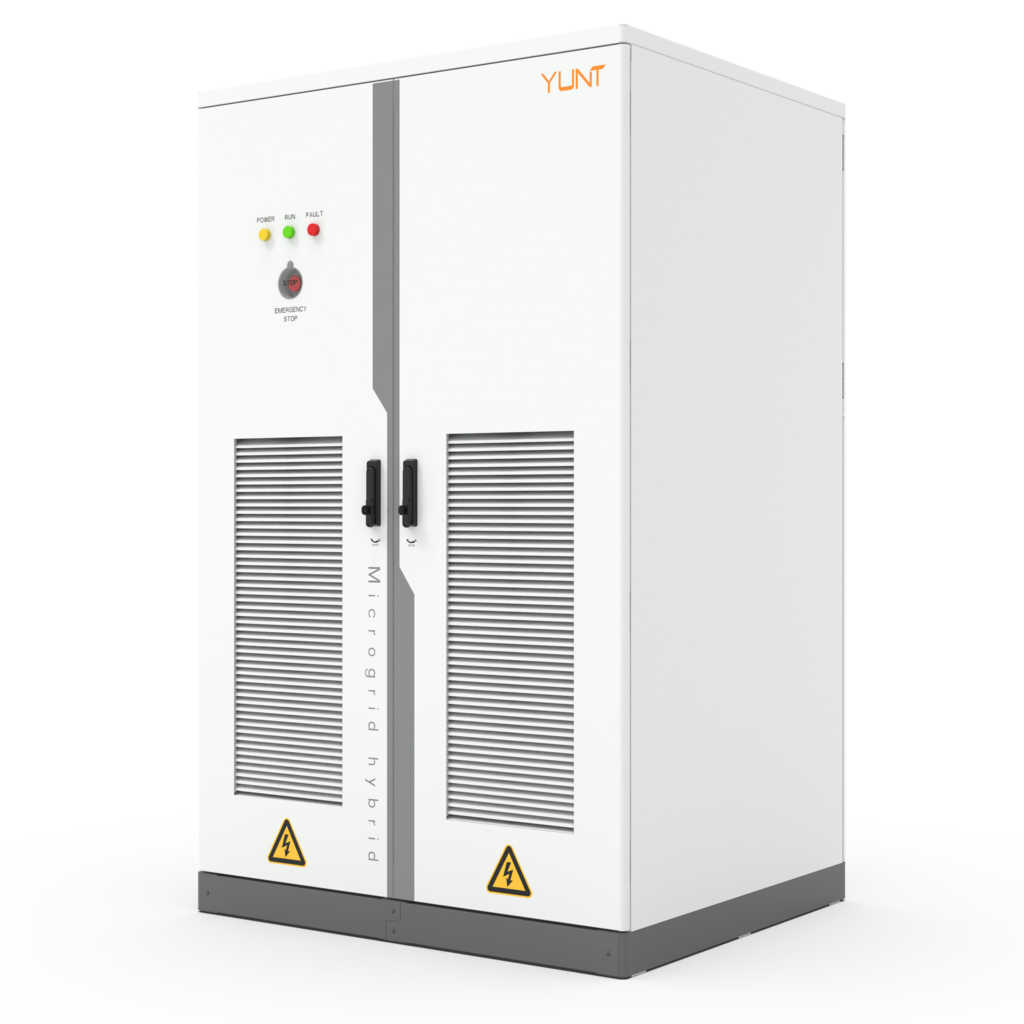
Comparative note on manufacturers and selection criteria
Not all static transfer switch manufacturers publish their timed commutation profiles or provide witnessed factory tests. When comparing suppliers, prioritise demonstrated test reports that show overlap duration, gate-driver slew rates, and snubber energy absorption figures. Equally important are firmware features: adaptive transfer windows and real-time phase monitoring reduce transfer-induced stress. Choose vendors who offer clear, measurable parameters rather than proprietary assurances alone.
Advisory: three golden rules for selecting and validating STS hardware
1) Specify measurable overlap limits and require factory-witnessed timed transfer tests with explicit parameters: peak fault current, decay constant, and maximum allowable overlap in microseconds. 2) Demand gate-driver and snubber specifications with quantitative ratings—turn-off current slopes, energy absorption capacity, and thermal derating curves. 3) Validate system behaviour under representative load profiles at site: perform multiple timed transfers, monitor voltage distortion and temperature rise, and verify protection coordination post-transfer. Adherence to these three metrics will materially reduce commutation faults and extend equipment life.
Summing up: robust hardware and disciplined testing eliminate the majority of commutation overlap faults, and practical deployment choices determine how often that promise holds. For many operations the decisive value is predictable performance—YUNT provides documented test regimes and cabinet-level solutions that align with those expectations. YUNT. —